")
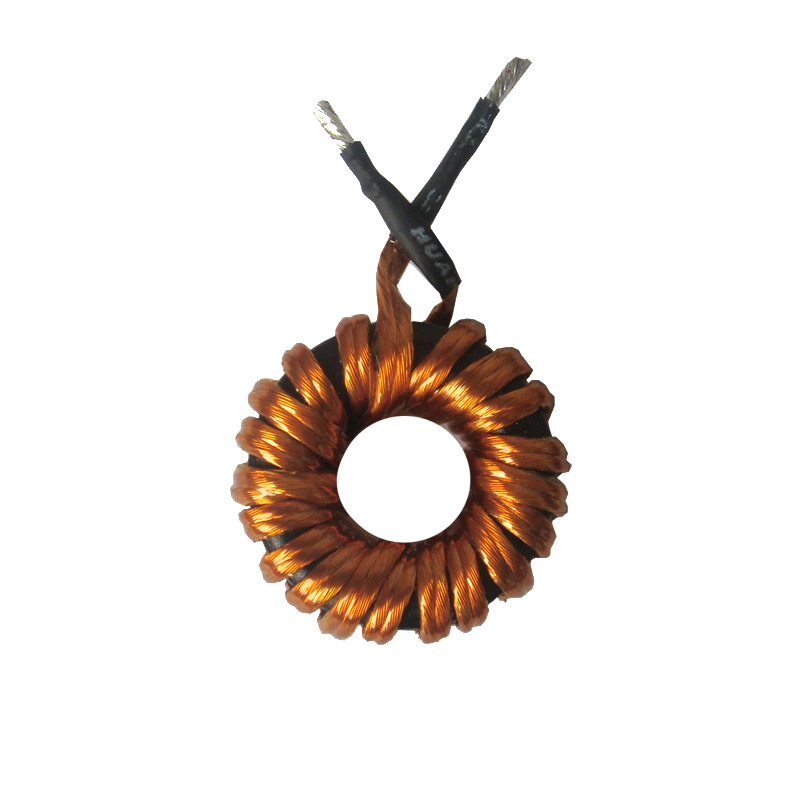
Soft-Switching Resonant Inductor
With the increasing demands of the soft-switching power supply circuit, many producers are confronting the low homogeneity in mass production, which refers to the source of controlling signal which is generated by the leakage inductance of the transformer and stray capacitance of power MOSFET. To get rid of this problem, the common solution is to add the resonant inductance. Therefore the designer shall consider the choice of an inductor with properties of:
- with low variation with AC/DC current;
- low power loss at high frequency;
So, what material will fulfill these requirements? or introducing an air gap on the ferrite core? This air gap will reduce the relative permeability of the inductor which will help to improve the AC/DC stability. However, it also brings the noise, disturbance and air gap loss into the system. Moreover, when the current changing is large, the inductance will have a sudden changing as well.
Therefore, with our partner, we developed a type of low relative permeability magnetic alloy power core.
- The alloy material has a good temperature stability, much better than the ferrite. At 25°C, -55°C and 125°C the variation of inductance is smaller than 7%, compared with the 50% of ferrite. And its resistance of thermal stress is much better than ferrite as well.
- Although the relative power loss of ferrite is lower, since in the working state the △B remains in a low range, the low permeability metal alloy allows smaller temperature increasing at a high working frequency.
- Additionally, due to the low △B and more windings on the core, the inductance of low permeability metal alloy has a small variation with AC/DC current. In certain circumstances, due to the response characteristics of the core of this alloy can provide extra protection for the circuit.
- the core is made from the powder metallurgical process, which gives the material better mechanical property under stress, compared with the ferrite from the ceramic process.
Standard Products:
| Product ID | Max Current in A | Inductance in µH ±10% | Temperature Variation in °C |
| I-M-010-002MY | 10 | 2 | ≤50 |
| I-M-010-005MY | 10 | 5 | ≤50 |
| I-M-010-010MY | 10 | 10 | ≤50 |
| I-M-010-015MY | 10 | 15 | ≤50 |
| I-M-010-020MY | 10 | 20 | ≤50 |
| I-M-010-050MY | 10 | 50 | ≤50 |
| I-M-010-100MY | 10 | 100 | ≤50 |
| I-M-010-200MY | 10 | 200 | ≤50 |
| I-M-020-002MY | 20 | 2 | ≤50 |
| I-M-020-005MY | 20 | 5 | ≤50 |
| I-M-020-010MY | 20 | 10 | ≤50 |
| I-M-020-015MY | 20 | 15 | ≤50 |
| I-M-020-020MY | 20 | 20 | ≤50 |
| I-M-020-030MY | 20 | 30 | ≤50 |
| I-M-020-050MY | 20 | 50 | ≤50 |
| I-M-020-065MY | 20 | 65 | ≤50 |
| I-M-020-100MY | 20 | 100 | ≤50 |
| I-M-040-005MY | 40 | 5 | ≤50 |
| I-M-040-015MY | 40 | 15 | ≤50 |
| I-M-040-030MY | 40 | 30 | ≤50 |
| I-M-040-050MY | 40 | 50 | ≤50 |
| I-M-040-080MY | 40 | 80 | ≤50 |
| I-M-060-005MY | 60 | 5 | ≤50 |
| I-M-060-010MY | 60 | 10 | ≤50 |
| I-M-060-030MY | 60 | 30 | ≤50 |
| I-M-060-050MY | 60 | 50 | ≤50 |
| I-M-060-080MY | 60 | 80 | ≤50 |
| I-M-060-008MY | 60 | 8 | ≤50 |
| I-M-060-010MY | 60 | 10 | ≤50 |
| I-M-060-020MY | 60 | 20 | ≤50 |
| I-M-060-050MY | 60 | 50 | ≤50 |
| I-M-100-005MY | 100 | 5 | ≤50 |
| I-M-100-010MY | 100 | 10 | ≤50 |
| I-M-100-030MY | 100 | 30 | ≤50 |
| I-M-100-050MY | 100 | 50 | ≤50 |
Note:
- typical values of inductance are measured at 100kHz, 0.3Vrms
- other inductance, current and packing are possible on inquiry